The FARR Coupling is utilised whenever a rigid connection is required in between the low pace shaft of the gearbox along with the head shaft of the conveyor, bucket elevator, mixer or any over-hung or suspended load. When sized appropriately, the FARR Coupling will carry the applica-tion torque, excess weight of gearbox, motor and swing plate. Within the case of the mixer, it’s going to carry the weight in the shaft and impeller, thrust forces and resulting bending moments.
Elements of the FARR Coupling consist of male and female piloted hubs created from 4140 alloy steel. The hubs are extended to assure 80% hub to shaft make contact with. Keeper plates are included for security. The 2 hubs are assembled with Grade 8 bolts and Grade À Prevailing Torque nuts. Typical coupling sizes possess a nominal torque range from eleven,300 to five,736,000 in-lbs. Greater sizes can be found according to the application.
Features
Heat Handled 4140 alloy steel
Male and Female pilots
Increased Torque Capacity
Grade eight Bolts / Grade ?¡ãC?¡À Prevailing Torque Nuts
Extended length via bore
Keeper Plate design and style
FARR Coupling Choice Manual
A. Obtain The next Data:
Application
Horsepower & RPM
Gearbox (Reducer) Ratio
Output Pace
All Shaft Sizes
Overhang Load
Lever Arm
(Distance from end of Gearbox output Shaft to Center-Line of Gearbox or Center Line of Gravity)
B.Calculate Application Torque:
T (in-lb) = ¡ê¡§HP x 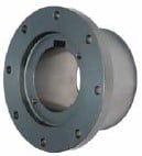 63025¡ê?/RPM
C.Calculate Design and style Torque by applying 2.0 Service Factor to application torque.
D.Select coupling with a torque capability equal to or greater than the Layout Torque from the Performance Data table.
E.Verify that the Bore capacity on the coupling will meet the application shaft requirements.
F.The Male pilot hub to always be used around the Reducer (Gearbox or Driver) shaft and the Female pilot hub to always be utilized within the Head (Driven) shaft.
G.Drive System Analysis must be performed by Application Engineering to verify coupling variety.