worm gear box assembly
EP has been designing and manufacturing reliable, high performance gearboxes for over 20 years. RW Series miniature right angle gearboxes provide high torque values with suprisingly low backlash in incredibly compact frames. Three gear ratios will be available to meet up the requirements of your specific application.
Order the EP RW Series worm gear box assembly you will need, request a quote, or e mail us for more information.
Worm Wheel Miniature Gearboxes
Our RW series miniature worm gear box assembly may be small, but it’s hard enough to handle demanding ability transfer applications. Constructed with machined aluminium housings and hardened metal input and result gears, they’ll deliver a long time of reliable performance.
Available in three standard output ratios and with several output shaft size options, it’s simple to find the EP right miniature gearbox for your needs. Each RW style worm gear container assembly provides proportionally substantial torque ideals (1.4 NM at 3,000 RPM) with suprisingly low backlash (maximum 2° backlash).
For full specs and Dimensional Parametric Search, see individual product listings.
The EP Advantage
High efficiency miniature right angle gearbox (up to 90% at 1,000 RPM)
Three gear ratios available: 5:1, 10:1, and 20:1
Extremely compact footprint: 1.5” x 1.5” x 1.08”
12.5 inch-lbs. output torque
Very low backlash (2° backlash maximum)
90° output angle
Maximum input speed: 3,000 RPM
Machined aluminum housing with hardened steel gears and oil-impregnated bronze bearings
Permanently lubricated
Made in the China
Mechanical drives take supplied torque and could increase or reduce that torque based on application. Also velocity is increased or reduced in proportion index G – GEAR BOXES – on blue – smallto the speed reduction ratio. EP includes a full line of gearboxes and quickness reducers, and the elements needed to build them, in a wide range of regular ratios and shaft options and also custom designs.
Helical, bevel, and miter equipment boxes provide options of rate reducers or rate increasers, and may be driven in either path. All EP worm equipment speed reducers and right angle drives are produced for high performance in a large spectral range of applications. Typically worm gear boxes are not used as acceleration increasers. The instances are molded glass-filled material making them extremely rugged and tolerant to corrosive conditions. They can be found in an array of ratios and are built with right hands or left hands worm gears. The output shafts may be sturdy or hollow, and load capacity is unaffected by path and rotation.
Worm gear quickness reducers are comprised of a good screw (the worm) that drives a wheel (helical gear) or one enveloping wheel and are found in mechanical applications which range from conveyors to exercise devices to robots.
Geneva mechanisms and assemblies are typically used to transform continuous rotary motion into intermittent rotary movement. The rotating drive steering wheel includes a pin that gets to right into a slot of the driven wheel advancing it by one step and a blocking disc that locks the powered wheel in position between steps.
Compact design
Compact design is among the key terms of the typical gearboxes of the BJ-Series. Further optimisation may be accomplished by using adapted gearboxes or unique gearboxes.
Low noise
Our worm gearboxes and actuators are extremely quiet. This is because of the very smooth working of the worm equipment combined with the use of cast iron and great precision on element manufacturing and assembly. Regarding the our precision gearboxes, we consider extra treatment of any sound that can be interpreted as a murmur from the 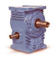 gear. Therefore the general noise level of our gearbox is definitely reduced to a complete minimum.
Angle gearboxes
On the worm gearbox the input shaft and output shaft are perpendicular to each other. This typically proves to be a decisive advantage making the incorporation of the gearbox significantly simpler and smaller sized.The worm gearbox can be an angle gear. This is an edge for incorporation into constructions.
Solid bearings in solid housing
The output shaft of the BJ worm gearbox is very firmly embedded in the apparatus house and is ideal for direct suspension for wheels, movable arms and other parts rather than having to create a separate suspension.
Self locking
For larger equipment ratios,EP-Gear’s worm gearboxes will provide a self-locking effect, which in many situations can be utilized as brake or as extra protection. Also spindle gearboxes with a trapezoidal spindle will be self-locking, making them well suited for a wide range of solutions.
Structural Features
The worm-gear reducer comprises of three main parts: housing, worm-gear and wheel.
The carcasses are made from GG-25 cast-iron, and are available for all types of gear-reducer. This make sure they are perform effectively under stressed circumstances, vibrations or any kind of setback that can’t be avoided through the assembly
The worm-gear is constructed of hardened and quench-hardened steel, with ground- on teeth sides, and the crowns made of DIN (GZ-CuSn 12 Ni2) centricast bronze, melted on steel. Because of the mechanical work of the two parts having top quality, excellent functionality and low noise amounts have been achived.
The output shaft is hollow, although it can be done to adapt a solid shaft.
The oil seals made of NITRILE BUTADIENE, according to DIN 3760, top quality bearings, an EPOXY- impregnated finish ( 2 components), and grey-coloured SINGLE LAYER ENAMEL finish ( 2 components) ( RAL 7672), supply the most competitive gear reducer available.
Size 63
In the size 62 of the MF series, worm-gear reducers, the output hollow shaft of diameter 30 has been included, that substitutes to the output hollow shaft with diameter 25, from size 62. This variant provides like reference size 63 and is born like answer to the demand of our costumers since, upon mounting better bearings in the result, bears greater axial loads that its analogous one in the MF-62 series. The rest of technical characteristic are identical to the its analogous in the size 62.
Assembly Position
In order to setup a gear reducer and also to make it happen efficiently, the next instructions must be taken into account:
It should be fixed on a flat surface in order to avoid either vibrations or tensions.
If undistributed loads or continued start-ups are foreseen, it is recommended to insert compensating couplings, connectors, torque limiters etc…
If the apparatus reducer had to be painted, the essential oil seals must be covered to prevent them from drying and losing their seal.
The device work of the fittings create in the output shafts need an ISO H7 or h6 margin for the hollow shaft.
Backdriving
It is smart to pay attention to this aspect when the apparatus reducer result shaft is driven instead of being a driver. Bearing in mind that one of the features of this worm-equipment reducer may be the fact that can’t be axle-driven by the output shaft (irreversibility), it is almost impossible to meet total irreversibility conditions, because of external elements such as vibrations, etc. That is why, when the application needs total irreversibility, it really is advisable to make use of external brakes with enough power to avoid slipping.
It could be said that the circumstances under which irreversibility can occur are the following:
• Efficiency < 0,55 (discover table of technical features).
Maintenance
This kind of gear reducer will get a permanent lubrication, so it does not need any kind of maintenance.
Lubrication
The lubrication of this gear reducer type is constant and comes as standard, with high quality refined oil which includes antirust and antiwear products with Fe, Cu and alloy protectors which has level of quality CLP DIN 51517-3, FGZ level 12, AP GL-4, US 224, AGMA 250-04; because of this its maintenance isn’t needed.